Editing objects on the map
This chapter describes the creation and editing of objects with different geometries.
The representation of the objects on the map is basically done according to MIL-STD 2525C. An "anticipation" of the MIL-STD 2525D can be found in the representation of civilian vehicles & equipment with the color "pink", as well as in the activities with the four black squares in each corner of the basic symbol.
With version 0.17.0 the Mission Task Verbs from the NATO Standard ATP-112, as well as national tactical symbols (Effect Verbs, Action Verbs - marked with "(AUT only")) were started to be implemented.
In ODIN some deviations tending towards MIL-STD 2525D are chosen where MIL-STD 2525C does not reflect tactical necessity and/or sensible reason (e.g. Direction of Attack as multi-point line instead of a "2-point line"; additional assignment of modifiers (e.g. with natural events, facilities etc.); selection of all Hostility Status with tactical graphics - point objects etc.)
General
The objects are distinguished according to their assignment or their geometries, because the creation and editing, as well as the contents of the properties window are aligned according to these in ODIN:
- units point objects
- weapons, vehicles, equipment (Equipments) point objects
- installations point objects
- activities point objects
- "SKKM" AUT national civil point objects
- tactical Graphics point, line, area and corridor objects
The first part describes the creation of objects on the map based on geometries (point, line, area, corridor).
The second part describes the input options (modifiers according to MIL-STD 2525C, additional fields, etc.) in the respective property windows of the objects.
Basic procedure for creation
-
The basic procedure in ODIN to create an object is the following:
-
Set active layer or set the desired "target layer" as the active layer (double click on the layer name);
-
open the map palette;
- enter search text (always refers to symbol name and hierarchy path);
- click with the mouse on the desired symbol in the area of the map palette;
- click with the mouse on the desired position(s) on the map;
- fill property window (opens automatically).
-
Creation based on geometry of the object
Point objects
After selection in map palette and click on position on map, the creation process is already completed and properties window opens.
To change the position of a point object, you click on it with mouse and move it to new position.
With Copy (STRG + C) and Paste (STRG + V) ODIN creates the object again on same position. When you click and move the object, the object is now visible twice on map. When copying, all entries already assigned to the object in properties window will also be copied.
Note that the copied object is always saved in the active layer (even if the "source" object is saved in another layer).
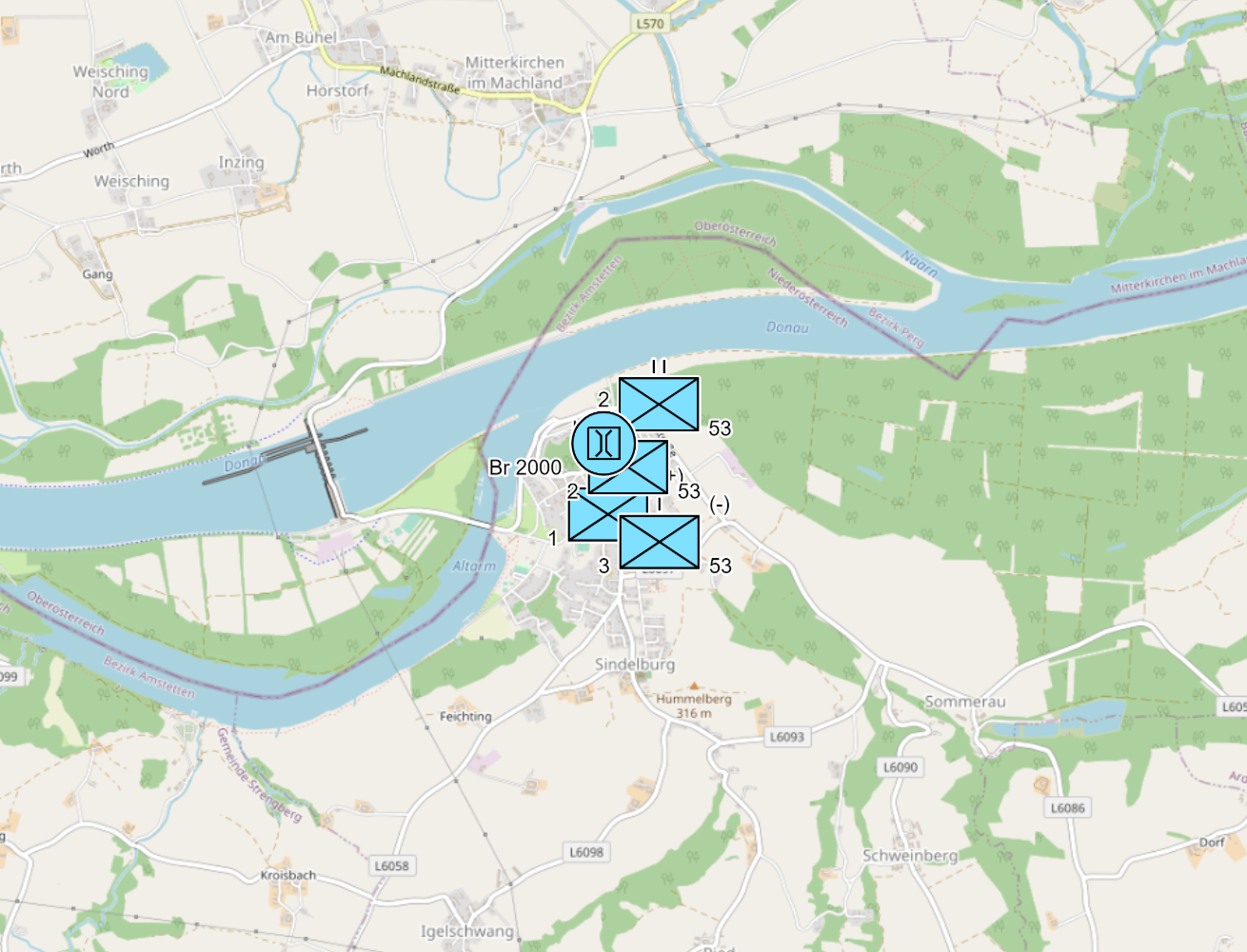
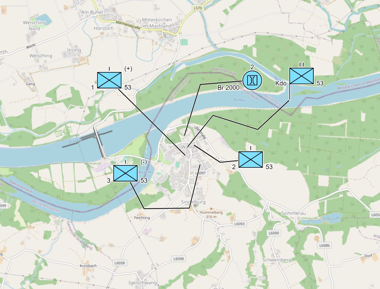
To improve the display of location, you can use the "Offset Location" function for point symbols. To do this, click on object, hold down the ALT key and then use the mouse to move the object to the desired position:
 |
 |
|---|---|
You can adjust the line of "Offset Location" by selecting object and then moving mouse over the line until a red circle appears. Now you can move the line with mouse and set a new point.
The second way is to select the object, hold down ALT key and click with mouse on position in map where object should be displayed.
To cancel "Offset Location" again, hold down ALT key and click on "Start Point" of "Offset Location".
Line objects
After selection in Map Palette and click on desired position on map you start to enter the line and add a new "section" with each mouse click. With a double click on map you finish the entry of the line object and properties window opens.
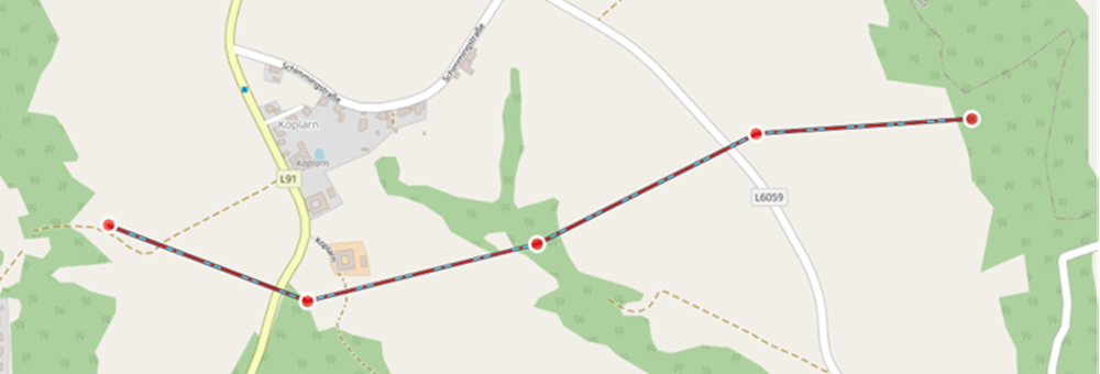
To change the position(s) of a line, select the line and with select a red point and move it with the mouse:
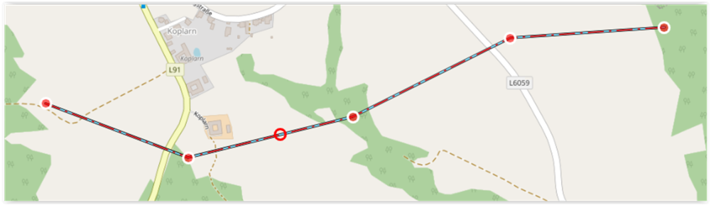
If you want to set a new point, move the mouse pointer onto the line until a red circle appears and move it with the mouse:
To move the entire line you have to hold down the SHIFT key.
To delete a single point you have to hold down the ALT key and then click on the red point you want to delete.
Copy (CTRL + C) and Paste (CTRL + V) behave analogously to the point objects.
Surface objects
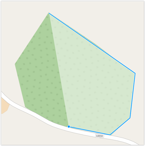
After selecting in the Map palette and clicking on the desired position on the map, you start entering the area and add a new "section" with each mouse click. When drawing the area, this area is highlighted by means of a transparent white representation. With a double click on the map you finish the entry of the surface object and the properties window is opened:
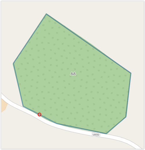
To change the position(s) of a surface, select the surface and choose one of the "corner" points and move it with the mouse.
If you want to set a new point, move the mouse pointer onto the line until a red circle appears and move it with the mouse:
To move the entire area you have to hold down the SHIFT key.
To delete a single point you have to hold down the ALT key and then click on the "corner" point you want to delete.
Copy (STRG + C) and Paste (STRG + V) behave analogously to the point objects.
Surface Area, rectangular
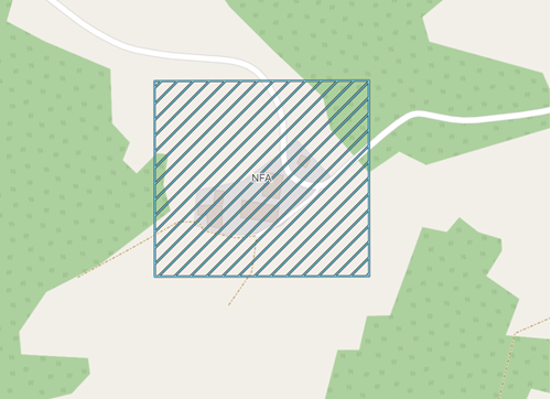
The rectangular surface area object represents a special form of processing (e.g. for the representation of the fire position areas such as ACA, NFA, ZOR, etc.).
After selection in map palette and click on the desired position on map the rectangular area object appears. The selected point with mouse on map is always the left upper corner point of rectangle.
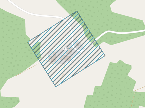
To change the size of rectangle, select rectangle, move mouse pointer to one of the corner points until a red circle appears and move it with the mouse.
If you move the mouse to one of the corner points until the red circle appears, hold down the CTRL key and move mouse afterwards, you can rotate the rectangle.
 |
 |
|---|---|
Corridor objects
After selecting in the Map palette and clicking on the desired position on the map, you start entering the corridor and add a new "section" with each mouse click. With a double click on the map you finish the entry of the corridor object and the properties window opens.
To change the position(s) of a corridor, select the corridor, choose a red point and move it with the mouse:
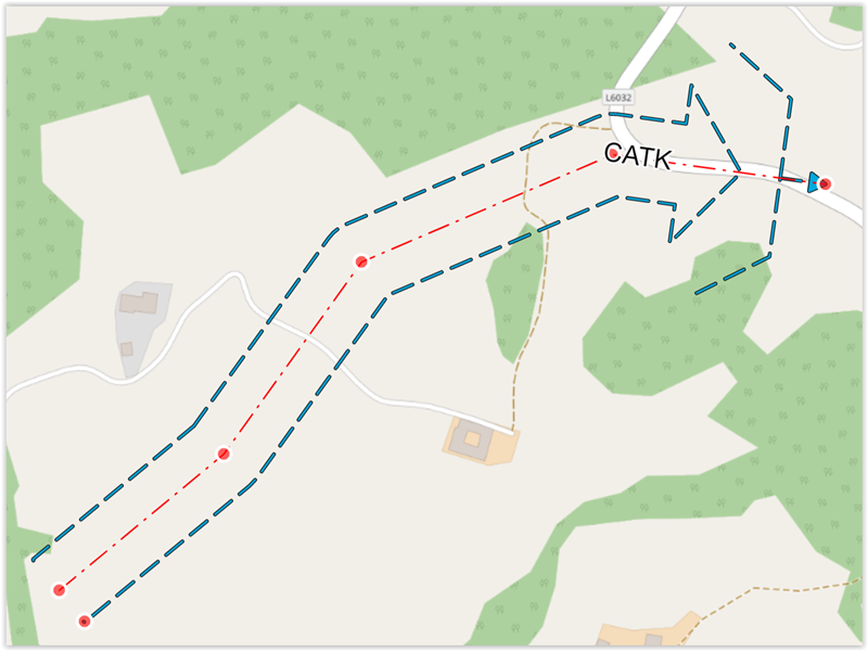
If you want to set a new point, move the mouse pointer to the red inner line until a red circle appear and move it with the mouse.
You can change the width of the corridor by moving the red dot on the side at the end of the corridor with the mouse.
In rare cases, the corridor's geometry might lead to invalid or degenerated visualization. In this case the corridor will appear with a yellow-black line and a note indicating that an invalid geometry has been created:
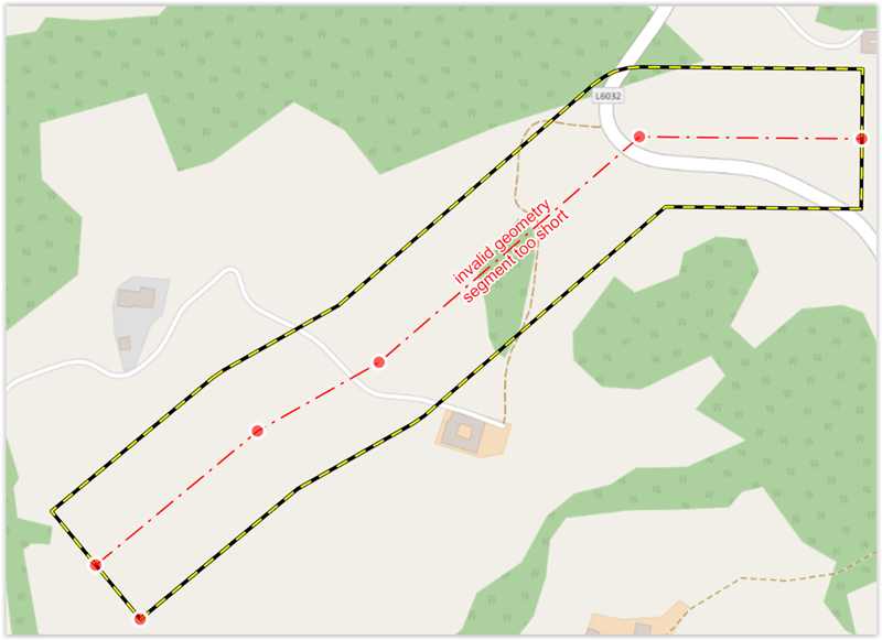
You can fix this by making the width of the corridor smaller or by changing the red dots accordingly. Tip: For most corridor types, the last/arrow segment must have a certain length to be correctly displayed.
To move the entire corridor you have to hold down the SHIFT key.
To delete a single point you have to hold down the ALT key and then click on the red point you want to delete.
Copy (CTRL + C) and Paste (CTRL + V) behave analogously to the point objects.